Laser cutting
Safety
Fire is wonderful and we wouldn't be where we are today had we not learned to harness it long ago however fire in our shops is something that we should do our best to minimize. Aditionally there are lots of harmful vapors that can be released as combustion byproducts so we need to be rather strict with what materials are allowed to be cut in our spaces and what ones should never enter the cutter. When in doubt always chat with your shop staff.
Types of lasers
Traditionally if you walked into a shop and saw a laser cutter it was almost always a CO2 based laser. This results in a laser wavelength in the infrared range where it is readily absorbed by things such as wood, plastic and glass. These machines generally are unable to cut or engrave any metal as the vast majority of hte beam energy is reflected by metals. Industrially there are many other laser wavelengths but recently lasers with different gain mediums have started to trickle down into the hobby market giving us fiber sources, UV sources, MOPA sources and better cheaper optics have allowed us to reliably focus to a much smaller spot size such that light metal cutting and engraving is now possible at the hobbiest scale for the first time which opens the doors to many new and interesting approaches. This is quickly moving to allow some of the work that would more traditionally require a water jet, a large expensive machine with non-trivial waste water disposal, to instead be done faster and cheaper on a laser.
Parameter search
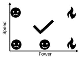
Now asking carboard to not light on fire as you blast it with enough energy to vaporize it sounds like a sisyphusian struggle but there is actually a relatively wide parameter space in which you get good cuts without risking sending your machine up in smoke. We (or at least I) can't take a mathematical approach to solving for a range of parameters that will cut your material so we must take an empirical one. Let's start my making sure we live in the "too fast to cut through but won't burn" regime. One assumprion that we will make to simplify the process is that our speed should be locked at 100% in order to finish the job as quickly as possible. This will increase our throughput which is very impportant for serial jobs in shops with few machines, and it turns our 2D parameter search into an easier 1D search. This is an assumption that will hold true for cardboard and even most acrylic on our lasers but it does start to fail on thicker, denser materials that take more time to cut. Say you only cared about 5% tolerance then optimizing a 2D search would require ~400 tests and comparisons to ~20 for a 1D search so even an imperfect assumption saves us a lot of effort. In other words we want to simplify this
To this
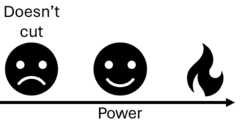
Now I won't give you numbers because that defeats the point of the exercise but we probably want to start around say 2% power and 100% speed and increase your power a couple percent at a time. This will feel a little disappointing at first as you won't cut through all the way but it won't be a ball of fire... Don't forget to make note of the nice engraving parameter space that you'll likely pass through as you iterate to cutting. It sounds funky but you can in fact engrave some pretty decent detail into cardboard.
Cardboard
Do remember that while kinda nice this is still cardboard. Load bearing structures are certainly possible but they take quite a bit of thought and finesse. Joint types might be a little more limiting but nice pressfits are possible. It is also quite anisotropic with different stiffnessess based on your loading direction and the orientation of the corrugations between the layers.
Feature size
There isn't a hard rule here but do remember the corrugated nature of cardboard. If you decrease your feature size beneath the corrugation pitch there is no guarantee that your top and bottom layers are actually connected together. Additionally very small features become a fire hazard so you might need to adjust your speed/power settings in order to safely cut intricate details.
Kerf
Kerf is an important feature in many subtractive machining operations which boils down to the width of material removed by your tool. In this case our tool is a beam of light so it is small but it isn't infinitesimal and if you don't account for it then your parts won't fit together as well as they should. The easiest way to measure the kerf is to cut an object of a known size and measure what the actual output is. Say I wanted a 1cm square and got a .95cm square then I would know my kerf is 5mm and if I offset my perimeters by +/- 2.5mm then my parts should come out the exact size that I want them. Why isn't this built in to the machine in 2026 given that the process is so simple? I don't know. There is some variance between whether you are keeping the positive or the negative and kerf can be a function of material thickness but getting at least close is pretty easy. I bet it would be a fun internship at Epilog or Universal though.
Parametric Design
What does this mean and why is it important again? Say hypothetically you need to make a box. You spend a while modeling everything in your cad package of choice and after a couple hours you have the world's best box. Once you're done you get a call asking if you could change the dimensions of that box a bit to add room for some other component that was forgotten about or you find that your joints were a little loose and you wanted to tighten them all up. In the best case scenario you have to figure out which sketches set the relevant parameters, find them in your timeline and make the edits then cross your fingers that everything rebuilds properly and you don't end up with missing references, tabs/slots that don't line up, and a pile of spaghetti the untangling of which can take as much time as simply starting from scratch. Well most CAD tools these days are also somewhat decent programming environments. When inputting a dimension instead of doing 10 cm you can do something like overall_width = 10 cm This might feel a bit clunky at first but I assure you it becomes very powerful. You can also do lots of math in the same panel. Something like (overall_width/num_connections)+kerf-tolerance is perfectly valid as long as you have all of these terms defined. Done properly lots of relative dimensions will let you make very flexible models that can build and rebuild in vastly different sizes and configurations without any issues. In order to access the list of these parameters from the whole model at once you can use the modify->change parameters button. Working this way has a little bit of a learning curve but the benefit far outweighs the input effort for all but the simplest of models.
Fits
How things fit together is a very well studied field with ample resources available to make sure that stationary things stay stationary and sliding things slide. This however tends to be done in more homogenous materials that are a little more predictable than cardboard but starting from numbers that work in other materials is certainly better than guessing. I usually use bolt hole charts as a rule of thumb and then adjust as needed if I find my fits are a little loose. This really should be done on the small scale as a group project which will then feed forward into your designs. A bit of effort up front can save you from hours of cutting out big complex parts only to realize that they're all trash because the tabs don't work and you need to start again. I try not to meddle in the process of an individual but some light steering here to avoid big sinks of wasted effort is an exception that I'll happily make.
Joints
The field of joinery is quite beautiful and very well suited for solid homogenous material. However cardboard is not solid nor homogenous so the possible options are more limited here. simple finger joints or tabs and slots are surprisingly robust and suitable for many projects.

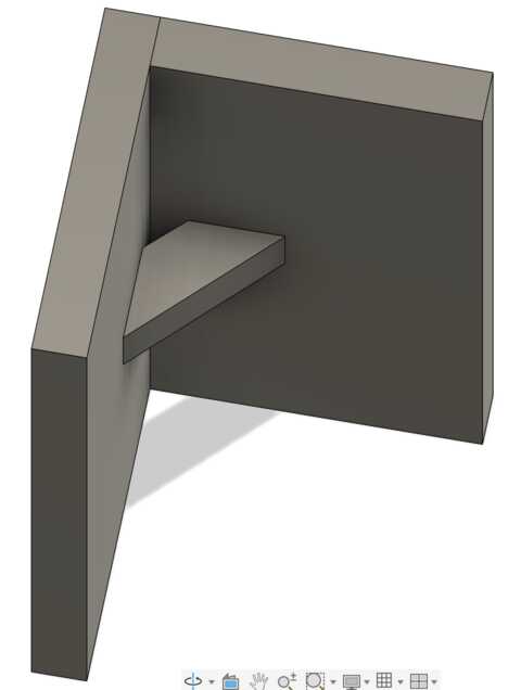
If you're worried about strength or fits at specific angles you can employ gussets like this for some extra help. A gusset is similar to an angle baracket but this will instead penetrate into the material that you are connecting. Here is a picture of it as a solid body.
And a cutaway so you can see what is going on inside.
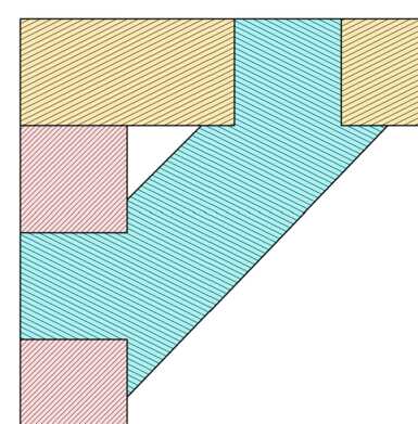
It is important that the walls of the blue gusset extend along the face of each piece. This ensures that there is a feature stopping how far you can insert the gusset which will help keep your walls square (or at your other designed angle) and will transfer load between the pieces.
Chamfers
When you finally sit down to assemble your parts you will often find that lining up and inserting one tab was much easier than doing a whole wall of them at once. Any little misalignment between the tabs and slots sums into a required insertion force that can be difficult to handle. Chamfers are one way to help with this. They are angles cut onto your parts in order to help guide it into place and you push it into the slot. While these are technically optional future you will really appreciate them! A better design of the gusset from above with chamfers on it might look like this.
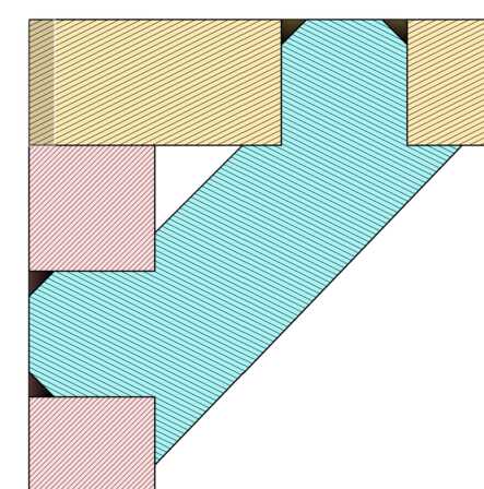
This won't have much affect on your final part strength and are very quick to implement using the built in chamfer tools and will pay off once you come to assembly time. You can do this on virtually every tab in your project not just ones for gussets.
Bendy bits
Perhaps the most fun part of this assignment is thinking through and making exceptionally flexible parts starting from a rigid material. This is another well studied field called flexure design but given the low stakes here you can abandon the mathematical approach and take a more artistic approach to engineering if you so choose. The guiding factors somewhat simplify down to minimizing strain which is defined as the change in length of a beam over its original length. essentially if we can spread the same bend over long windy pieces rather than short stubby ones we will get a more flexible material and fewer kinked sheets. The specific choice of pattern and the dimensions of it are important factors in determining how a piece is going to bend that I'll come back with more detail on in a future iteraton of this page.
Assembly order
One gotcha to be aware of when designing multi-part assemblies is the ability to actually assemble them. It is certainly possible ot design something such that there is no way to fit the last puzzle piece into place because the previous parts are blocking its insertion. In the case of the gusset above if I were to attach the horizontal and vertical wall together then try to push the gusset into place it would have to enter in on a 45 degree angle and would simply not be possible. If I were to insert the gusset into one wall, then add the new wall the problem would decompose into a single insertion direction and assembly would be possible. Thinking through these problems as you design comes with experience.
Actually using the machine
Machine trainings should always be done in person but here I'll list some important bits that either tend to be forgotten or are simply worth saying twice.
Going too fast
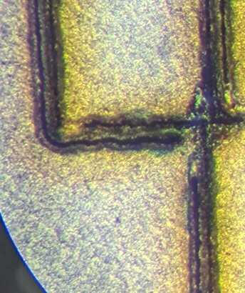
There are 2 main cases where you won't want to run your laser cutter at 100% speed. The first is simply once you've maxed the speed and the power and your material is still not being cut in one pass. Then you simply reduce the speed in order to spend more time dumping energy into the same spot on the material hopefully burning/ablating it away and managing to make it all the way through your material in one go. The next case however is more interesting. If you are doing very finely detailed work you might find that the control loop around your machine has some ringing in it which causes noticable deteoriations in performance. Below I've included some preliminary testing that I was doing on cutting circuits with a cheap fiber laser. Those are supposed to be straight line segments but you can see the obvious ringing as the machine shakes around. In this case reducing the speed could be necessary if you really want to push the boundaries of what is possible. Here it was taking multiple passes to cut through and the lack of proper tracking in the corners caused them to simply not heat the copper enough to cut through.
Cutting twice
Another edge case worth being cognizant of is simply sometimes you need to cut twice. If you haven't disturbed your material nothing is stopping you from just running the same job again if you determine that your first attempt didn't cut all the way through. These are imperfect machines cutting imperfect stock and sometimes you just gotta go again. Warped stock changes the where the focal plane sits in your material which changes the spot size and the energy density which could cause it to not complete the cut. Natural materials can have knotty or extra dense areas that change the physical properties, the laser cartridge can get a little toasty and derate its power to help compensate etc etc.
Some inspiration
I hate whitespace. I much prefer bounded problems and a bit of rails in order to help get the creative juices flowing. The real inspiration for this site was to begin documenting a series of demos that like-minded folks could play with before they get started on their assignment for the week to help seed cool ideas and the "but what if..." thought process. Everything up to this point has mostly been an afterthought that I figured I might as well document while on the journey to this destination as I thought it could come in handy. This is one of the weeks in which the need for this isn't particularly strong so perhaps I'll just use it as a deeper dive into flexible bits and pattern choices.
Error 404- Splines not found
Corel draw (the art program we use to run the laser) is imperfect. Sometimes you'll find that arcs/splines either are missing in the imported image or were distorted when they were opened. I assume it's because DXF has multiple versions and the default from Fusion and Corel don't always agree. Someone smarter than me can problably fix this or run some script that detects the disagreed upon parameters but I have a tried and true work around for the vast majority of situations. I pop into the conference room and open up Solidworks (a wonderful cad program with a bit of a rougher learning curve), import that DXF into a new sketch, extrude it into a solid part and turn that part back into a dxf. This solves pretty much every issue we've run across and is usually faster than guessing which image format is going to be happy.
The Assignment
The assignment for this week is:
group assignment:
• do your lab's safety training
• characterize your lasercutter's focus, power, speed, rate,
kerf, joint clearance and types
individual assignment:
• cut something on the vinylcutter
• design, lasercut, and document a parametric construction kit, accounting for the lasercutter kerf
• extra credit: design it to be assembled in multiple ways
• extra credit: include elements that aren't flat
• extra credit: engrave as well as cut
Let's break this down. You will receive copious instruction for the safety training that will be lab specific so I won't go into it here. The process for laser characterization will vary by machine so I won't go into it much here but the general idea is to play with these parameters and see how your results change.
We'll dive into more specifics on the individual design. Vinyl cutting documentation is housed at https://ampennes.github.io/htma_demos/vinyl/ so we'll skip that for now.
Learning to speak Neil can take a bit and here we will go word by word.
Design This means you have to create the files. You can't pop onto the internet and grab someone else's files. It would be acceptable to do something like import images of something that you want to make which you then trace around in your CAD program.
Lasercut This assignment is about learning to use a digital fabrication machine as much as it is about designing the parts themselves so you cannot do something like print out your part design on paper and then cut them out with hand tools.
Document Put very simply in this course you are graded by Neil. Neil's vision of you is simply the snippet that you document and push to your webpage. If you have solved cold fusion but not written it down you will get no points. You don't need the world's prettiest webpage simply good written descriptions and instructions and properly compressed images for each assignment will get you a good grade in this class. Missing images or descirptions will cause you to lose points which is very sad. Filling these pages as you go like a notebook is an easy recipe to success here.
Parametric This needs to be done in a CAD tool. You can't get by making parts in illustrator or another less capable tool like that. You'll need a parameter table so that you can edit a variable and have all your parts rebuild. You could have every element be parameterized but at a minimum I strongly suggest your tab/slot width be assigned a variable. That way if you find that your parts don't fit quite right you can simply edit 1 or two lines, automatically cause all your parts to rebuild appropriately, then just export your files and cut again!
Construction kit The intent behind this assignment is for you to design a series of discreet pieces which can be assembled in multiple ways to create multiple objects. This one has wiggle room as many people instead pick a physical object and make a series of parts that assemble into it. This tends to not be an issue.
Accounting for kerf Again the kerf here is the width of the laser beam. If I don't find this parameter all my holes will end up too big and any positive part will end up too small causing your fits to be sloppy. Solve for this once, offset everything by it and you will be good to go.
Worked Example
Ok now lets actually go through making something. I'm going to start by solving for my laser kerf. After doing my machine training I cut a simple 1cmx1cm square. Using a pair of calipers I found that my part actually measured only 9mmx9mm meaning I will need to offset 0.5mm on all side in order for my parts to be true to size. This number is an example, you will likely solve for something substantially smaller.
Now that I have a value for kerf I am going to open up my design software and start sketching some things out. For this demo we're going to keep things simple and just do a few shapes that link together in multiple ways.
Square
Triangle
Hexagon (the bestagon)